FAQ
How to transfer files from a computer to the HMI?
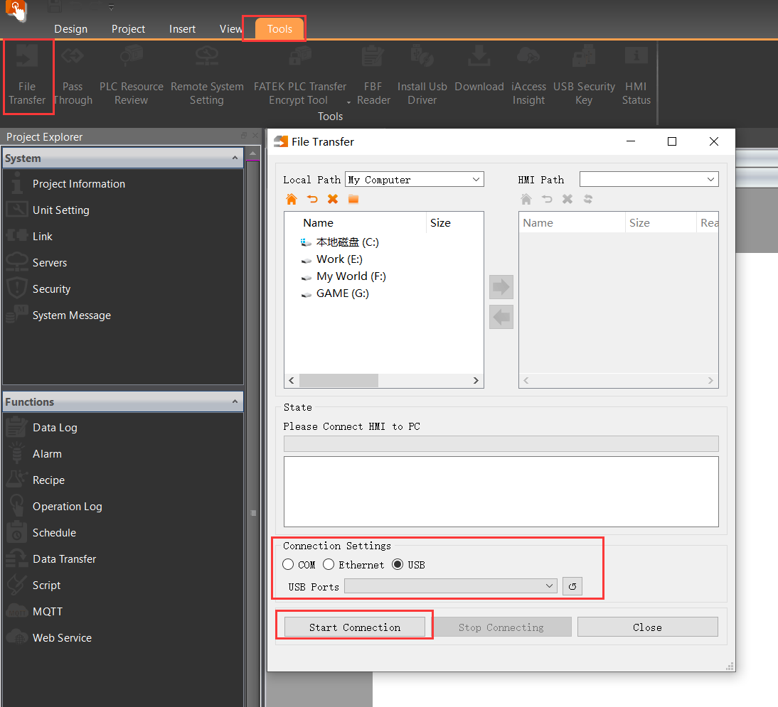
① Connect the PC to the HMI (via USB or Ethernet) and select the "File Transfer" function in the HMI software.
② Choose the files from the computer in the transfer interface and upload them to the designated storage path on the HMI.
How to enable HMI's FTP function for accessing internal files from a PC on the same networ
.png)
.png)
.png)
① Enter the HMI backend (long-press the upper-right corner during power-on) → "Server" → Enable "FTP Server", then configure username and password.
② Note the HMI's current IP address in the network settings.
③ Connect HMI and PC to the same LAN. In Windows File Explorer, enter ftp://username:password@HMI_IP to
How to test the project program without a physical touch screen?
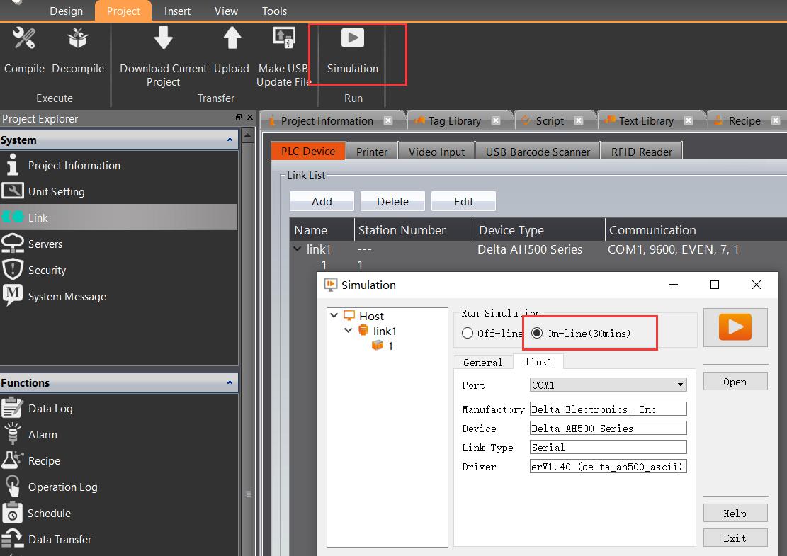
Use the "Online Simulation" function: Navigate to Project → Simulation → Online Simulation, then configure the corresponding slave device and COM port on the PC.
How to implement hierarchical access control for screen interfaces?
.jpg)
.jpg)
① Enable security: Customize passwords and assign access levels in the interface.
② Set the corresponding access level in screen properties to restrict operations to authorized users.
How to switch screens using scripts or registers?
.jpg)
.jpg)
① Use the change_bs() function in scripts (e.g., change_bs(screen_number)).
or
② Set a control register for screen switching: Assign a register in "Device Settings" → "Control Address", then modify its value in scripts to switch screens.
What should be noted when using the HB1 back-mounted unit for HMI selection?
The length of the HB1 must not exceed the rear-mounting dimensions of the HMI.
How to check the meaning of communication alarm pop-up codes?
.jpg)
Search for "communication error codes" in the HMI software's Help section (click the question mark icon in the upper-right corner).
How to select floating-point data types in scripts?
.jpg)
.png)
First, add the required floating-point addresses in the Tag Library, then select the corresponding tags in the script for usage.
How to use the Text Library for language switching on the interface?
.jpg)
.jpg)
.jpg)
①Set the group number to match the required language groups (e.g., 3 for Chinese, English, Japanese). Select the corresponding cells in the table below to modify text styles and translations.
②Then, choose text items in the text control.
③The default control address for text display switching is $U:V203000. Adjust the current Text Library group by modifying the "word" value of this address, e.g., write 0, 1, 2 via a word button to switch groups.
How to enable the alarm pop-up window function?
.jpg)
In the advanced settings of the alarm configuration, select "Display Window Screen".
How to replace the HMI startup image?
.jpg)
In the "Download Project" window, select "Defined Startup Options" and choose the corresponding image.
How to recalibrate the HMI touch point position?
.png)
.png)
Long-press the upper-right corner during the HMI power-on to enter the HMI backend, then select the calibration interface
What do Flash, RAM, internal user storage, and project memory represent in the HMI specifi
Flash memory and memory refer to the space of the temporary storage registers such as XNV, NV, V, etc.
Internal user storage refers to the space where the formula will be output to an internal location, which can be seen through file transfer and is considered internal user storage.
Project memory refers to the capacity of the project plus the firmware.
How to touch multiple buttons at once
.jpg)
.jpg)
① Use the multi-function button option and add the corresponding button effects.
or
② Use overlapping buttons to place multiple buttons on top of each other. And check the option for "Touch overlapping buttons at once" in Device Settings - Basic.
Why does the data content of data collection or formula disappear after the power is turne
You need to check the backup memory option to perform power-off retention (automatic data retention for a 1-minute interruption).
How to set up the barcode scanning function of the HMI?
There are currently two methods:
- In the software, go to [Project Management → Link → Enable USB Barcode Scanner] and set the corresponding address. Subsequent scanning actions will automatically write to the set address.
- Use [Text Input Display → Allow Input Selection Barcode Input]. This method requires activating the dialog box first, and then the scanning action will write to the address.
In common application scenarios, method one is more commonly used.
How to draw a perfect circle on an HMI?
First, drag an ellipse object from the toolbox. Then, select the ellipse and in the top interface's [Design - Basic Functions], set its height and width to be the same to obtain a perfect circle shape.
How to implement copying the internal registers of one HMI to another?
- Using a mini-USB port for operation
First, upload the HMI data content that needs to be saved. In the software, select [Project - Upload], check the box for uploading internal register data, and confirm. Once the file is uploaded to the computer, download it to the other new HMI by selecting [Project - Download Current Project] and checking the box for [Update Internal Register Data]. Select the previously uploaded file and download it.
- Using a USB flash drive in the HMI backend [Press and hold the corner after the HMI is powered on]
In [System Backend - Other Settings - Backup]
First, insert the USB flash drive into the HMI where the data is to be saved and perform the export operation.
Then, insert the USB flash drive into the other HMI where the data needs to be downloaded and perform the import operation.
How to upload an HMI project using a USB flash drive
When you don't have a computer at hand and want to retrieve a project from an HMI, you can use a USB flash drive to upload it.
First, create a new folder on the flash drive and name it 'upload'. Then, insert this USB into the HMI, and it will ask if you want to upload the project. Choose to confirm and wait for the process to complete.
Subsequently, in the software, select the decompile function to obtain the project content.
How to download an HMI project using a USB flash drive?
Users can create a project as a file for downloading with a USB flash drive, making it easy to transfer HMI applications to the same model of HMI. The function to create a USB update file can be found in the [Project] tab in the upper toolbar of FvDesigner. Click on [Create USB Update File], and the dialog box will open, allowing you to directly enter the setup page.
Here are a few points to note:
-
If the USB capacity is larger, it may take a longer time to appear the inquiry dialog box.
-
To improve software performance, if you are using a version of FvDesigner earlier than V1.3.29, please be aware that using a USB flash drive with a .ufrp file to upgrade the project may encounter unstable situations. The solution is to use FvDesigner V1.3.29 or later version to download the project again, and then use the USB flash drive to update the project.
-
After version V1.3.29 or V1.4.7, the USB flash drive update file created has the file extension .ufrp2. If an HMI that has not been downloaded with FvDesigner V1.3.29 or later version is used, it will not recognize the USB flash drive update file created after V1.3.29 or V1.4.7. The solution is to use FvDesigner V1.3.29 or later version to download again.
Put the prepared file into the USB flash drive and insert it into the running HMI. A dialog box will appear, select OK, then select the project you want to update and press confirm, the system will start the update.
How to recalibrate the HMI touch control points
When the touch screen is powered on, press and hold the upper right corner for a long time to enter the HMI backend, and select the calibration interface. Follow the on-screen instructions to complete the cross-click operation, and do not turn off the power in the middle. After completion, wait for the HMI to restart.
How to modify the project's model
After opening the FvDesigner project, click on Project Management—Project Information—Model—Change Model or Direction.